
Roller rail with bottom mountinig
Technical specifications
Standard sizes:
25, 30, 35, 45, 55, 65
Code:
V202
The manufacturer reserves the right to make design and specification changes. To place an order, specify the carriage and linear guide part numbers according to the order number.
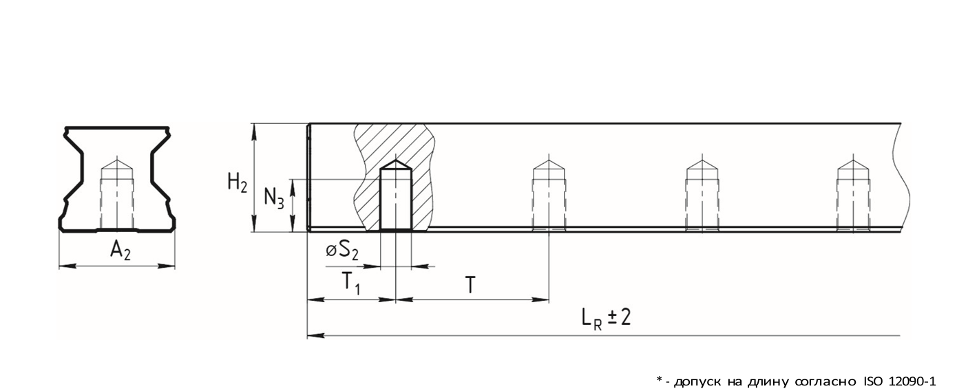
Dimensions of V202 rail
| Standard size | Dimensions | ||||||||
|---|---|---|---|---|---|---|---|---|---|
| A2 | H2 | LRMAX1 | N3 | S2 | T | Time1 min | T12 | M (кг/м) | |
| 25 | 23 | 23,4 | 6000 | 12 | М6 | 30 | 13 | 13 | 3,1 |
| 30 | 28 | 27,8 | 6000 | 15 | М8 | 40 | 16 | 18 | 4,3 |
| 35 | 34 | 30,8 | 6000 | 15 | М8 | 40 | 16 | 18 | 6,3 |
| 45 | 45 | 38,8 | 6000 | 19 | М12 | 52,5 | 18 | 24,25 | 10,3 |
| 55 | 53 | 47,55 | 6000 | 22 | М14 | 60 | 20 | 28 | 13,1 |
| 65 | 63 | 57,85 | 6000 | 25 | М16 | 75 | 21 | 35,5 | 17,4 |
Note:
1. Size H2 – with protective tape
2. Size H2 – without protective tape
3. Maximum length of a solid rail
4. Recommended size with tolerances of ±0,5
Dimension T1 is equal to the distance from the end of the guide to the center of the first mounting hole. If a specific dimension T1 specified by the customer is not specified, the dimensions of the manufactured rails are determined according to the following formulas:
| Number of mounting holes in the guide | Determining the size of T1 using z | Comparison with the value T1 min from the catalog |
|---|---|---|
|
1) n = LR / T
2) Round n to the nearest integer down
3) n + 1 = z
T – distance between the centers of the mounting holes
LR – rail length
n – calculated number of distances between holes
z – number of mounting holes
|
4) T1 = (LR − T(z − 1)) / 2
T1 – calculated distance to the first mounting hole
T1 min – minimum size T according to the catalogue
|
4.1) If T1 ≥ T1 min
use T1 from formula 4)
4.2) If T1 < T1 min
calculate T1 using formula 5)
5) T1 = (LR − T(z − 2)) / 2
|